
Fluid simulation of the main rotors
To start, let’s go over the new rotor design!
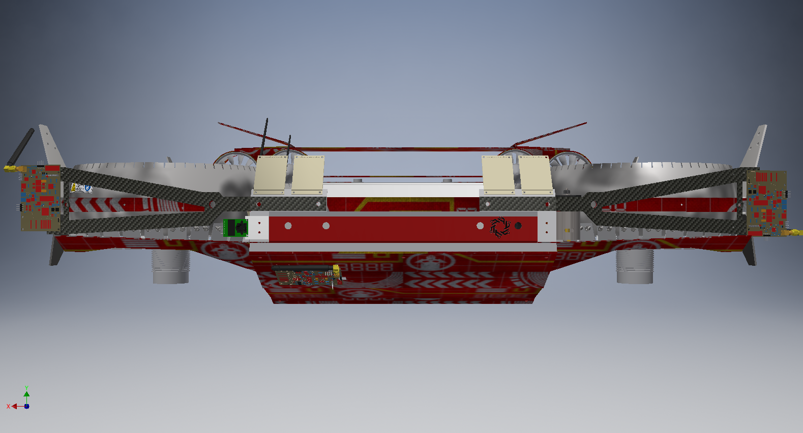
Here is my updated design of the rotor.
As you may notice, a single rotor module actually contains 2 separate (and equivalent) units.
It is a 9-blade ducted turbine-style propeller and to be honest, I have no idea how well it will work. But that’s what simulations and hardware iterations are for, right?
The current CAD files are not complete, as I only have gotten as far as designing the core components of the rotor and I have not began designing the structural elements or casing.
These parts will be created later, once I have validated this design and proven it can work. The reason for this is because I do not want to spend a lot of time making a nice case and structure and later have to redo it all if I need to drastically change the geometry.


You also may notice that the fan is shaft driven. This choice was made because while it is heavier, I believe it will be far more reliable if designed properly. The drawbacks of this (besides weight) are an increased cost.
I have not finished the structure to hold the shaft system yet, but as you can see, the gears and shaft are all modeled and fit together quite well.
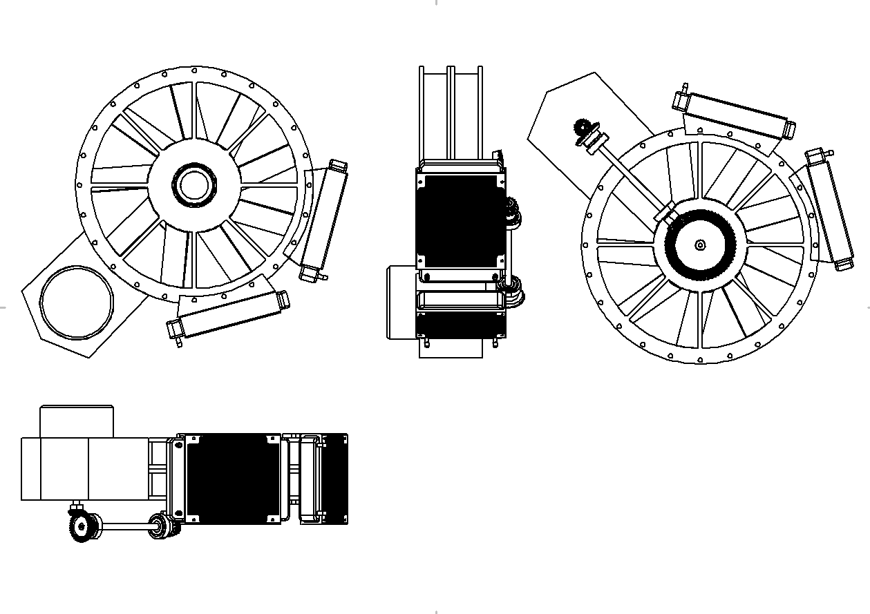
And here is a nice drawing I made showing a single rotor unit at multiple perspectives.
I used Solidworks for Makers for this design.
Here is the rotor, without the duct. You can clearly see the velocity flow lines (via Paraview SurfaceLIC plugin), and the tip vortex structures.


Obviously, the tip vortices will be reduced with a shroud, but I ran this simulation simply as a control experiment, to see the propeller without any shroud around it.
I need to make my boundary conditions more accurate, since this was merely a test run and I used inputs that are likely not realistic. Additionally, I need to test for various (faster) angular velocities.
Currently I am having quite a difficult time meshing the propeller with the rotor shield around it. I believe this is due to very small cells between the rotor tip and shroud inner wall causing the rotating mesh to “grab” the static mesh and “drag it”. However, this is just a hypothesis, and I need to further study this problem to come to a valid conclusion.
Stay tuned for the next simulation runs!

